That word has many meanings and connotations – from the mob providing “protection” (for a fee, of course), to using protection during sex, to any number of others. Today I’m going to talk about keeping my Magic Box safe from the predatory practices of the trails I like to run.
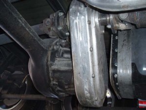
Here’s the current situation: In order to get power from the middle axle to the back one, I had two options. I could use a pass-through low-pinion 9-inch axle in the middle, and another low-pinion axle in the back, or I could use a gear-driven 1:1 transfer box on the middle axle (again with a low-pinion 9-inch), with an “over-the-shoulder” output yoke to power the back axle (with a high-pinion 9-inch). For multiple reasons, I chose the gearbox option, knowing that it would hang down below the bottom of the middle axle’s differential.
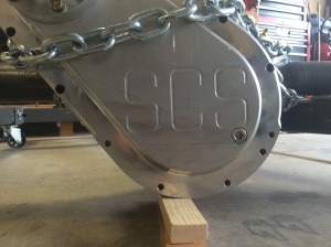
What I didn’t know, and had no way to foresee, was how far below the differential the box would hang and how difficult it would be to build a skidplate to protect it. This photo (which you’ve seen before if you’ve been following me), although not of my axle, gives you a good idea of the challenge:
After much thought, Robert (at R&W Custom Sliders and Offroad) suggested I swap the third members in my two back axles and bolt the Magic Box to the high-pinion gearset. That would move the Box up 4.5 inches and get it out of harm’s way, and would make building a skidplate for that axle vastly simpler. It sounded good to me, but there were a couple of things I wanted to verify with the Box’s maker (SCS Gearbox) before going that route (I didn’t want to get everything taken apart only to find out we couldn’t do what we wanted to do).
The first question I had was whether the pinion shaft had been modified at all. I didn’t *think* it would have been, and I couldn’t see any reason why it *should* have been, but since I had never seen it, I didn’t want to make any assumptions. I was assured that, while the pinion bearing support had been machined (to fit the Box instead of a seal and yoke), the pinion shaft itself had not been touched.
The second question I had was whether I could lay the Box over more horizontally without having lubrication issues. Since it’s designed to go on a low-pinion axle, the Box’s centerline is angled at 45 degrees, allowing the output yoke to clear the center section and the axle tube of a standard 9-inch axle assembly. But by raising the bottom of the Box 4.5 inches, I don’t have to worry about the axle tube any more, so I wanted to know if I could lay the Box over and thus reduce some of the height increase at the top end. SCS said I might have to play with oil levels somewhat, but they didn’t see any problems.
So here’s the plan: Bolt the Box (with the modified pinion bearing support) to the high-pinion gearset, and use that assembly on the middle axle. The low-pinion gearset will go on the back axle. While everything is apart, the Box will get a new set of bolt-holes drilled so that it can be mounted more horizontally – say, somewhere around 20 degrees above horizontal, instead of 45 degrees. This accomplishes the following:
- The Box’s lower end will be 4.5 inches higher than it is, which will put it well above the bottom of the axle’s third member and will get it out of the way of the rocks. Instead of 8.5 inches of clearance, I’ll now have 10-plus inches.
- The Box’s upper end will be about 1 – 2 inches higher than it is (due to the more-horizontal orientation). This alleviates the issue of getting the upper end *too* high and maybe sticking up into the tub somehow. We may still have to make some changes in a crossmember and/or build a tunnel for the Box, but it won’t be as bad as if the Box still sat at 45 degrees.
- The Box’s upper end will be a couple of inches closer to the passenger-side framerail than before, reducing the operating angle on the driveshaft yokes. [I had originally planned the Box’s yokes to be directly behind the transfer case’s yoke, but I didn’t know / remember that the drivetrain was offset in my Jeep, so when it was installed centered in the new frame, they didn’t line up.]
- Laying the Box over more horizontally will actually help with oiling. This picture shows the current level (the horizontal penciled line) and the new level (the angled one). There really isn’t much oil in the Box, and I think having the extra volume will provide a sort of “insurance policy” for the gears and bearings, without it being overfilled.
There are three downsides to this. One is so minor that it’s hardly worth noting, and is that the Box’s drain plug will no longer be at the exact lowest point of the Box. But it’s still so close that it won’t have any practical effect. The second is that, instead of the axle-to-axle driveshaft being nearly horizontal, it will now be about 5 – 6 inches higher at the front end than at the back end. But as it’s about 40 inches long, the operating angles shouldn’t be too severe. The third one is that the rearmost pinion / yoke is now potentially vulnerable to rocks and damage. I’ll alleviate this with a skidplate, and may eventually buy another high-pinion assembly to move things back up and out of the way. Maybe. Eventually.
I took both axles to Tucson Differential on Tuesday and expect them back in about 3 weeks (due to other work ahead of me, and the fact that they’ll have to send the Box out for drilling).
In other news, Robert let me know that he was ready for the CJ-6 tub, so after dropping the axles off at Tucson Differential, I loaded up the tub on Robert’s trailer and delivered it to him.
There isn’t a whole lot of the existing sheetmetal that we’re actually going to *use*, but it provides a good template from which to build the custom tub. And the parts we *will* use are indispensable – at least to me.


